Actuators for dexterous and agile robots
Content
- What is a robot?
- Is Actuator a big deal?
- Gearbox- The Culprit
- Motor control loops
- Passive compliance
- Pan-Cake Shape
- Conclusion
- References
What is a robot?
A robot is a bunch of actuators connected by a link(a structure) which should do some task. Actuators, being one of the fundamental elements of a robot, will determine the core capabilities and limitation of a robot. Thus a thorough understanding of the actuator will help us to optimize it based upon our requirement. In this article, we restrict ourself to Electromagnetic Actuator (Motors), since it is the most widely used one and has a higher energy efficiency compared to others like hydraulic, pneumatic, etc. Our goal is to understand various factors which influence the performance and figure out the optimal choice for robots.
Is Actuator a big deal?
It should just spin with some torque, right? what else would be expected. Well, traditionally automation and industrial robotic arms are fixed inside a cage where all the things are architecture as per the requirement. This mean there was less uncertainty and they didn’t come in contact with an unknown object. Everything was like an orchestra and the problem was reduced to finding the correct set of motor commands to do a particular task satisfying some constraints (like time, cost, power, etc.). For these type of problem, yes it should spin to a position with enough torque. Usually, this was achieved by numerous trial and error and finally hard coding the values in real-time. The actuator was designed to maximize the torque by having huge gearbox like shown below.
![Actuator Design in Automation, Source[1]](https://ajaygunalan.github.io/projects/asset/past/motor/automation_design.png)
Good for automation, but when it comes to general purpose robotics, we expect it to touch and manipulate objects like us and to be with us side-by-side safely, which demands actuators to be compliant, back-drivable, energy-efficiency and force transparency (ability to sense output torque from motor current). This can’t be achieved with pure position control and huge gearbox. If we did apply the same principles’ which worked for automation, the result will like below:

In fact, you can see more failures in this video of DARPA robotics challenge where the robot failed to do a task which seems trivial to us. The possible reasons for failure are huge gearbox, pure position control, lack of compliance(some were rigid like bricks) and bad control algorithm(won’t cover about it here). Let us delve into each of the reasons briefly.
Gearbox - The Culprit
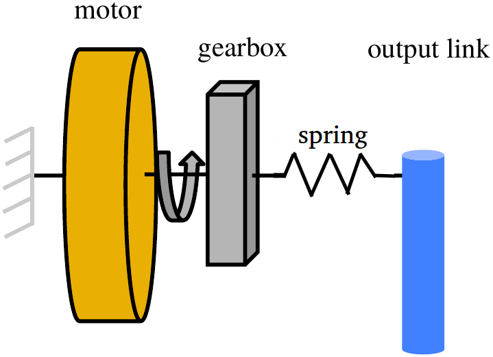
Gearbox is a power transmitter, used to increase the torque by decreasing the speed. Addition of gearbox induces various factors such as reflected inertia, backlash, internal stresses, coulomb, viscous friction, and stiction in the gear train. These non-linear effects hide forces acting at the output from being sensed by the motor causing motor current to be a poor indicator of output torque. Direct-Drive means directly coupling the load with actuator completely removing the gearbox. This overcomes all the drawbacks of the gearbox but increases the weight and volume of the motor due to higher torque requirement. Thus there is a trade-off between force-transparency and reflected inertia, torque requirement. Thus by having single-stage, back-driveable gears with low reduction ration(5-10), we can achieve a decent compromise between torque requirement and force transparency, impedance. We call this Quasi Direct Drive.[1]
Motor control loops
If you have ever done a simple line following a robot, you would probably know that there is something called motor driver which in essence applies the required voltage based upon the user command. Based upon the driver we can give different commands such as position, velocity, current(torque). No matter what command you give, ultimately it boils down to applying a voltage to the motor. The value of voltage will be determined by the error between the desired value and actual value. This means that for each loop (say velocity), there must be a particular sensor measuring it.
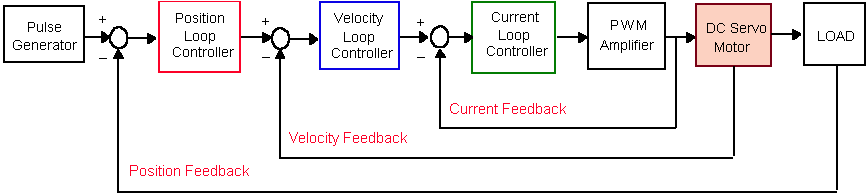
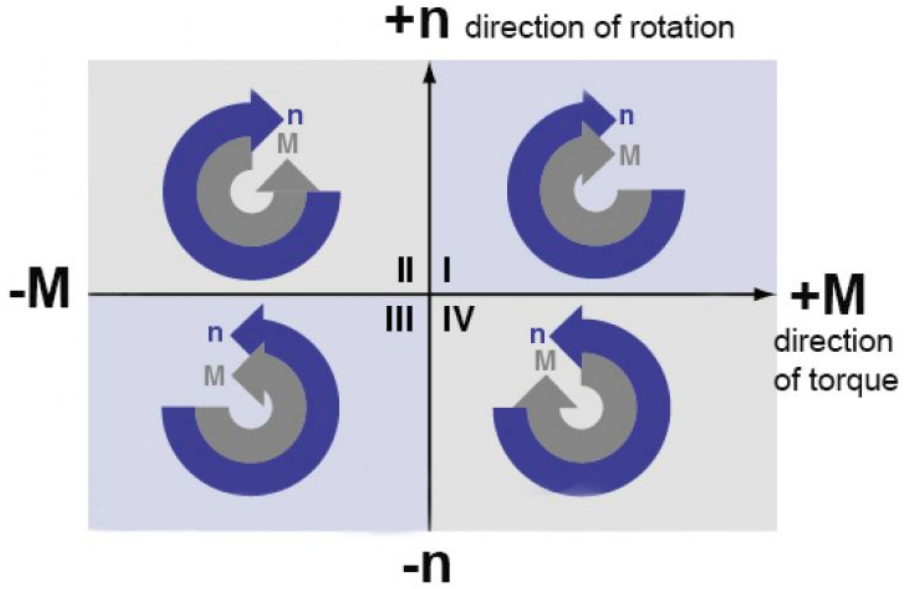
There is a reason behind why current is the inner-most loop because they are closer to the voltage(intuitively) and inner-loop operate (5-10) times faster than the outer loop. A motor drive can include any combination of three types of control loops—a position loop, a velocity loop, and a current. The bandwidth, or response time, of the system, is a measure of how fast it responds to the changing input command. As you might have guessed the inner loops have higher bandwidth. While higher bandwidth generally provides stiffer motor performance, decreases error, and improves transient response time, there are also drawbacks to high bandwidth in systems. Specifically, the higher the bandwidth, the higher the frequency at which the motor responds to disturbances, which typically requires higher accelerations and forces. Power dissipation has a squared relationship to force, so any increase in bandwidth significantly increases power dissipation (i.e. heat), and therefore, the temperature rise of the motor. Thus an optimal bandwidth must be chosen based upon the requirement. In addition to that, Motor drivers are also classified as 1Q or 4Q drivers. 1Q allows the motor to be operated in quadrant 1, and 3, allowing the motor torque and speed to be controlled in the same direction. Whereas 4Q allows all the four quadrants to be controlled and thus making active electromagnetic braking, regenerating current form the motor to the battery, possible. Thus a sufficiently high bandwidth 4Q motor driver is a must.
Passive compliance
Compliance can be added mechanically(using springs, damper) or virtually by conrol algorithm which can vary the stiffness and damping on the fly. So it seems that virtual spring is better because it gives variable stiffness. Not necessarily, mechanical spring makes control a bit complicated, but they are of enormous use when it comes energy efficiency. They store the sudden high impact force and can be reused in the next cycle. So, in essence, we should select the passive compliance for a baseline value and use the software on top it for fine-tuning.
Pan-Cake Shape
When we say pan-cake shaped motor, it means motors whose \(r_{gap} > L_{axial}\), where \(r_{gap}\) is the radial gap between center and rotor and \(L_{axial}\) is the axial length of the motor. The reason is torque density increases with \(r_{gap}\). But it doesn’t mean we can increase the \(r_{gap}\) indefinitely as torque per inertia is inversely proportional to \(r_{gap}\). So a compromise has to be made. In general \(r_{gap} > L_{axial}\) and should look like a pan-cake shape for having a higher torque density.
![Gap Radius, Source[2]](https://ajaygunalan.github.io/projects/asset/past/motor/r_gap.png)
Conclusion
Thus, we need a sufficiently high(optimal) bandwidth, 4Q control driver with pan-cake shaped motor, quasi-direct-drive and compliant-actuator so that the robot is capable of performing highly-dynamic maneuvers like us.
References
[1] S. Kalouche, “Design for 3d Agility and Virtual Compliance Using Proprioceptive Force Control in Dynamic Legged Robots,” PhD thesis, Carnegie Mellon University, 2016.
[2] S. Seok, A. Wang, D. Otten, and S. Kim, “Actuator design for high force proprioceptive control in fast legged locomotion,” in 2012 IEEE/RSJ International Conference on Intelligent Robots and Systems, 2012, pp. 1970–1975 [Online]. Available: http://ieeexplore.ieee.org/document/6386252/. [Accessed: 12-Sep-2018]